Context
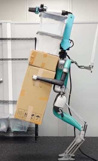
The Laboratory for Intelligent Design and Autonomous Robots (LIDAR, Dr. Ye Zhao) builds and studies legged and humanoid systems. One project was a custom auxiliary arm that mounts onto an Agility Robotics Digit humanoid. The arm and the humanoid were the lab’s; I did not design either. My work was the arm’s end effector, tactile-sensing prototypes for that end effector, and much of the arm’s wiring and assembly.
Gripper redesign
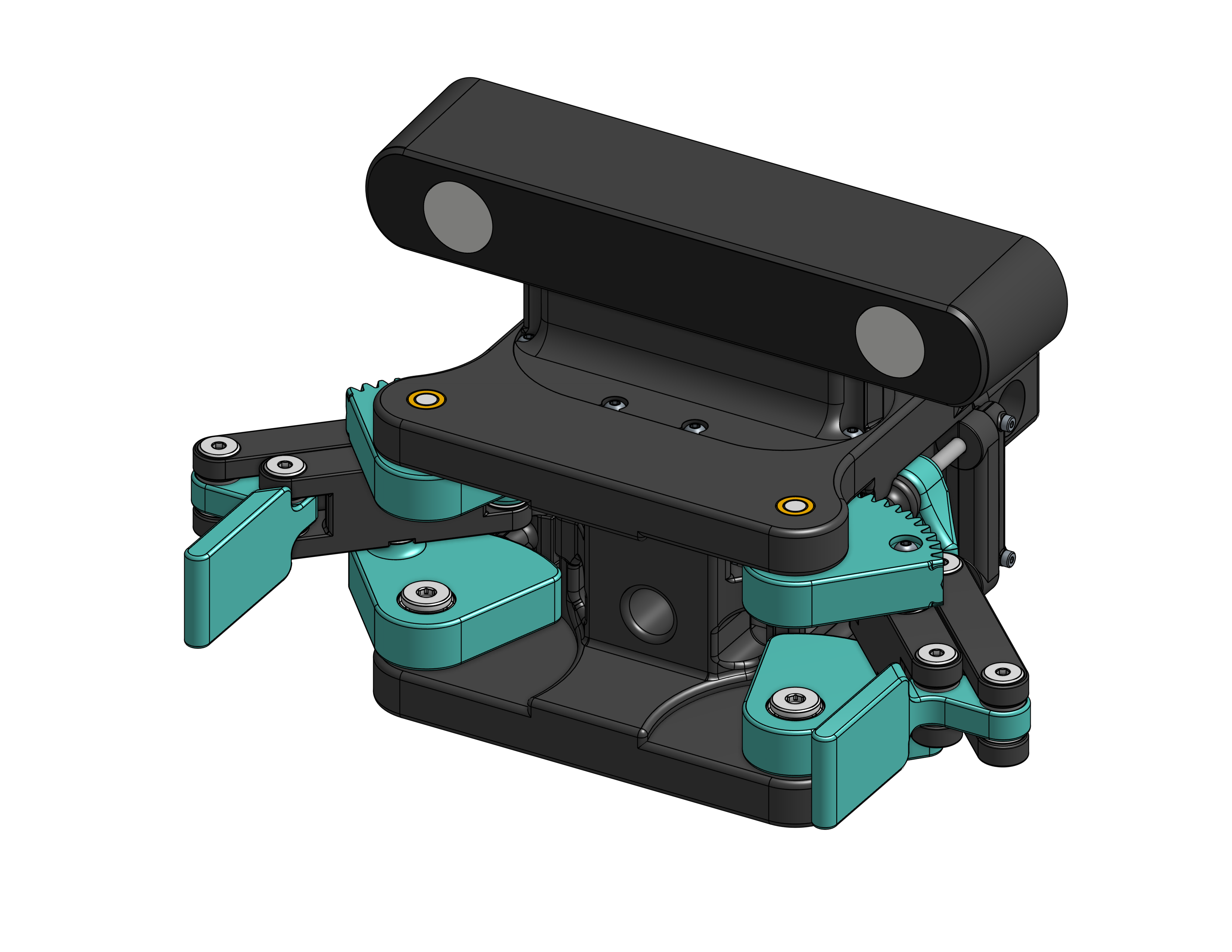
The arm’s original gripper was a rack-and-pinion parallel jaw with backlash, a singly supported rack, and visible flex under hand loading. I replaced it with a dual-servo crank–four-bar driving a linear slider on rails: two 3.5 Nm servos through a 1.8:1 reduction, 6.6 in of jaw stroke (2 in more than before), roughly 325 N theoretical closing force at servo stall, in the same 6 in footprint, at 1.9 lb including the ZED2 camera. The symmetric linkage removes the gear-mesh failure mode and puts load into the rails rather than the rack. Parts were 3D printed for prototyping; metal versions of the high-load parts were planned but never made, and the gripper was not mounted on the arm or Digit before the work ended. The full mechanism writeup is in the gripper case study.
Tactile sensing (prototyped, unfinished)
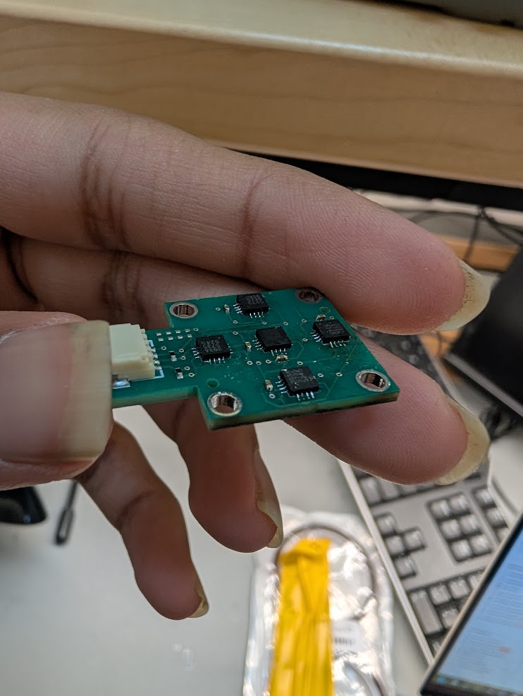
The fingers were designed to carry compliant magnetometer-based tactile pads following the eFlesh approach: magnets embedded in TPU cut-cell microstructures, with contact deformation read as field changes by MLX90393 magnetometers, ten per finger. I designed the finger and pad geometry, ordered the magnetometer array PCBs, and partially assembled them. The sensing subsystem was not completed or validated before the work ended, so there is no force-reconstruction result to report.
Auxiliary-arm integration
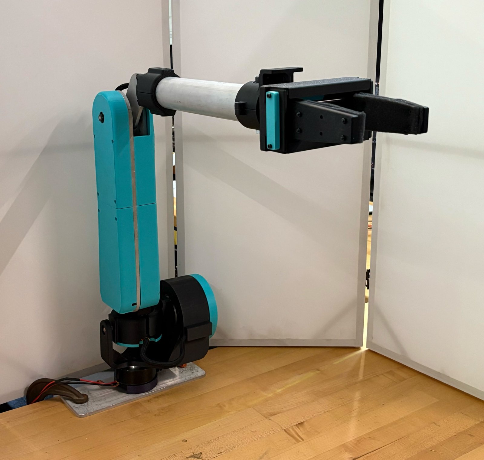
Most of my time on the arm itself was electrical. I fabricated and assembled the XT30 power and CAN wiring harnesses: routing along the arm, soldering, and connectorization. I assembled arm hardware and handled electrical/mechanical integration as revisions came through. During testing I supported humanoid calibration and motion validation: positioning, zeroing, and hardware setup. To be clear about ownership, the arm’s mechanical and control design was other people’s work; mine was the wiring, assembly, and integration.
Outcome
The gripper mechanism design and part fabrication were completed, but the gripper was never mounted on the arm. The tactile-sensing work stopped at partially assembled PCBs. The research thread wound down in May 2026 when the graduate student leading it graduated.