Humanoid Gripper
Overview
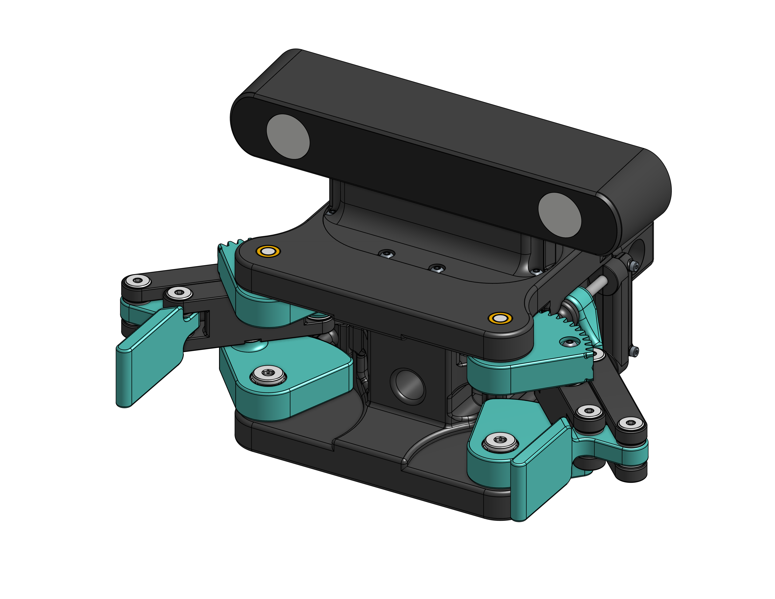
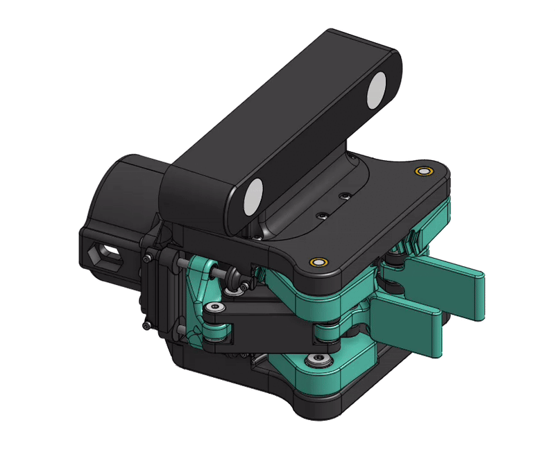
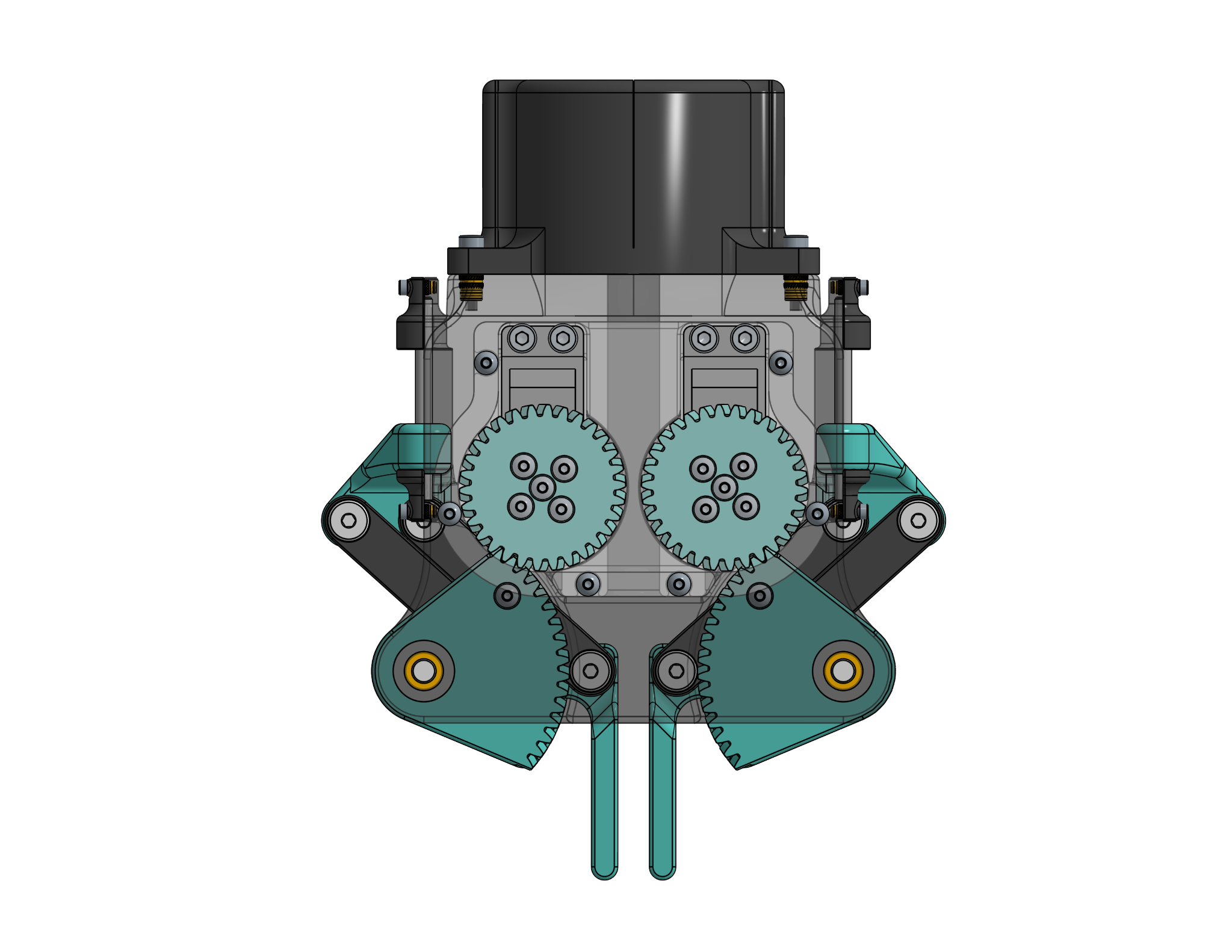
Redesigned the primary end-effector for LIDAR’s custom humanoid auxiliary arm (installed onto an Agility Robotics Digit humanoid). The previous design used a rack-and-pinion mechanism with limited stroke and structural flex.
The new architecture replaces it with a dual-servo crank–four-bar driving a linear slider, increasing stroke, stiffness, and enabling integrated tactile sensing.
Previous Design
- Rack-and-pinion parallel jaw mechanism
- Idler pulleys to maintain mesh
- Linear shafts for guidance
- Press-fit linear bearings (omitted in early prototypes)
- 54mm stroke
Primary issues:
- Backlash and mesh sensitivity
- Singly supported rack
- Assembly and tolerance complexity
- Structural flex under manual loading
Redesign
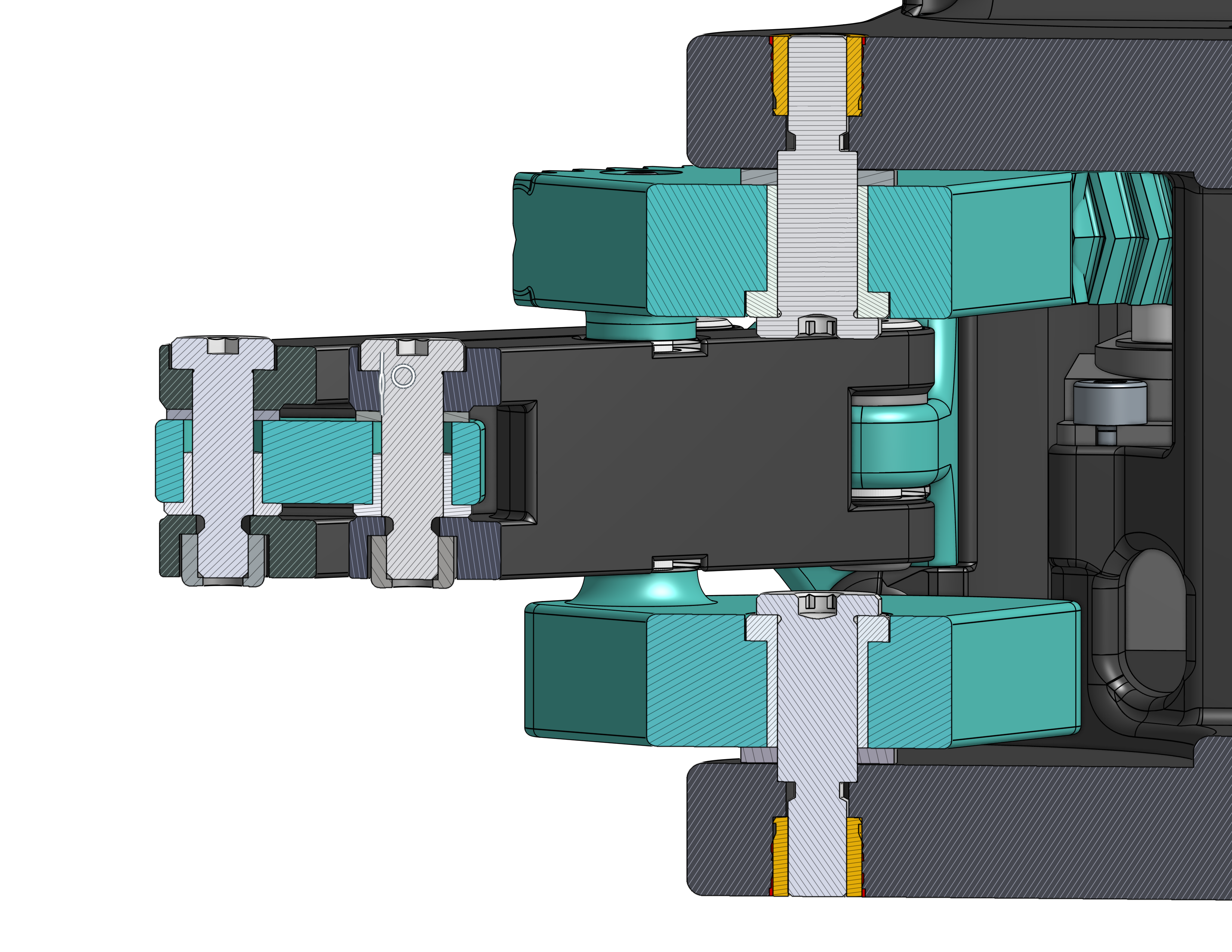
The new design uses a dual-servo crank–four-bar driving a linear slider.
- 2× 3.5 Nm servos
- 1.8:1 reduction
- Linear rails with bearings for constrained motion
- 6.6” total jaw stroke (+2” over previous)
- ~325 N theoretical closing force at stall
- 6” overall width (same footprint)
- 1.9 lb total mass (including ZED2 depth camera)
The crank-slider architecture removes gear mesh failure modes and distributes loading symmetrically.
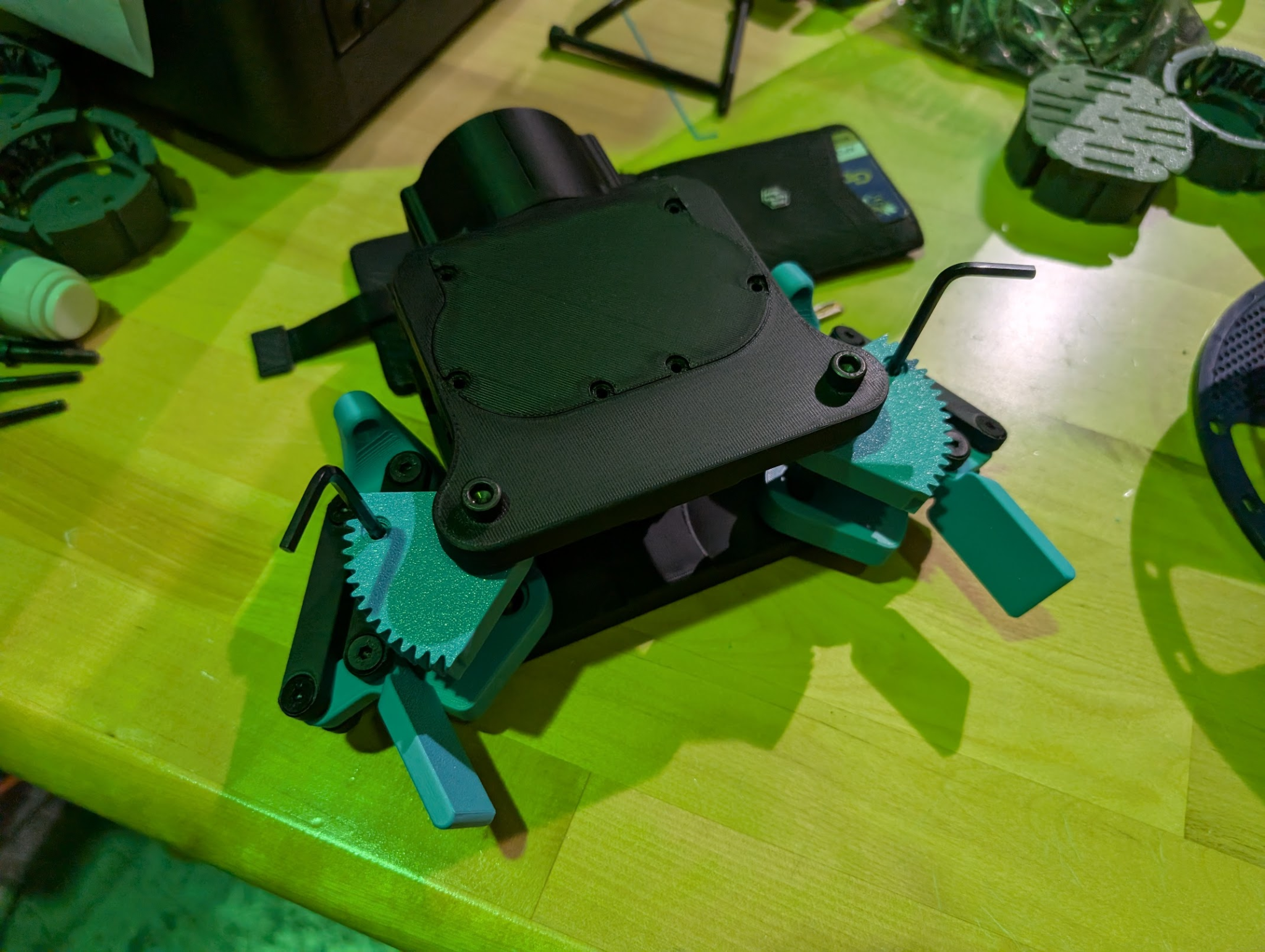
All components are currently 3D printed for prototyping, with plans to transition high-load elements to metal after validation.
Tactile Integration (Planned)
The gripper is being designed to incorporate compliant magnetometer-based tactile pads following the magnetic microstructured sensing approach following the magnetic microstructured sensing approach introduced in eFlesh (project website).
The approach uses embedded magnets within deformable TPU microstructures, with magnetic field variation measured by MLX90393 magnetometers to infer contact forces.
Planned configuration:
- 10 magnets and MLX90393 magnetometers per finger
- TPU cut-cell microstructured pads with embedded magnets
- Internal wire routing through a central tunnel
- Modular finger interfaces for rapid swapping
Current Status
3/19/2026:
- All part design and fabrication complete!
- PCBs in process of being assembled (writeup on this “process” soon…) - 1/5 complete
- Wiring diagram and control components ordered from Adafruit
- Parts largely arrived
2/16/2026:
- CAD largely complete
- Fingers with integrated compliant tactile pads, sensor cavity, and wire routing pending
- Version 1 parts printed
- Version 2 with camera mount, improved back rail support pending
- Fasteners and other commercial-off-the-shelf parts ordered
- Magnetometer array PCBs ordered partially assembled from JLCPCB
- Magnetometers ordered from Digikey
More to come soon!