Context
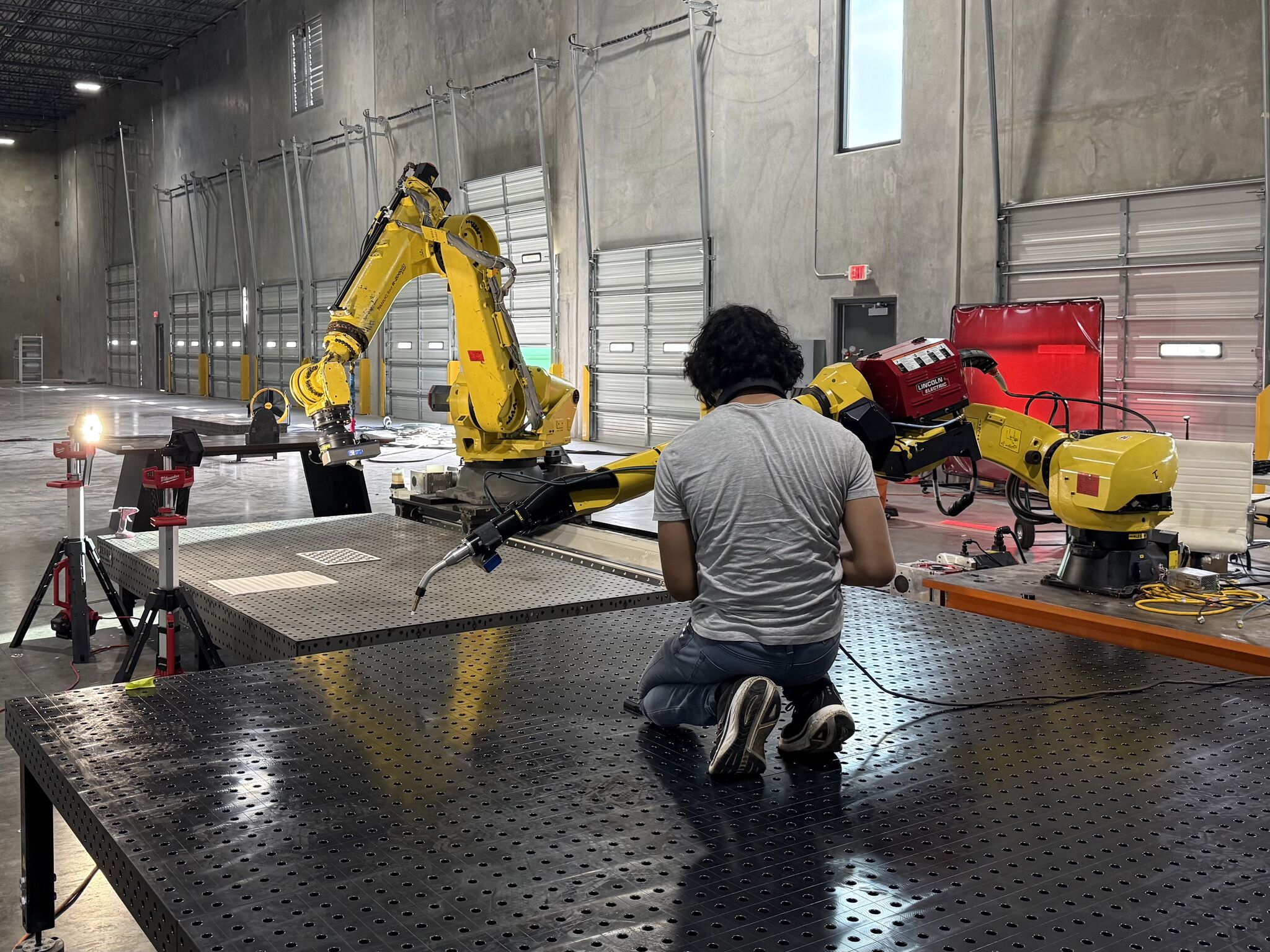
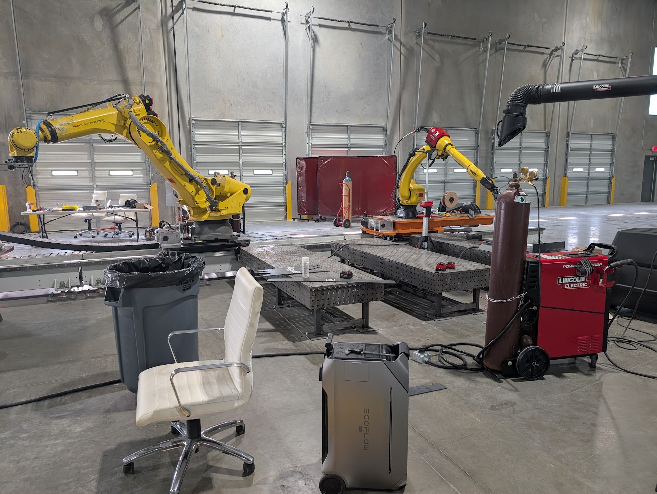
Valstad Shipworks is an early-stage company in Austin building robotic automation for shipbuilding. The system I worked on is a cell in which two FANUC M-710-class robots, carried on a Güdel RTU (linear axis), weld steel ship panels. I was the robotics engineering intern for summer 2026 on a small team, and the work covered both the physical cell and the software around it.
The pieces below are one workflow: panel geometry arrives from CAD, software turns it into parts, markings, and weld plans, the robots execute in a cell whose geometry has been calibrated to match the model, and telemetry records what happened so a run can be replayed and inspected.
Physical cell
- Operated the robots from the teach pendant, and defined and calibrated tool center points (TCPs) after each end-of-arm tooling change.
- Calibrated the work table and cell geometry so the frames the software plans in matched the physical cell.
- Swapped and integrated EOAT; integrated force and other sensor hardware on the robots.
- Set up, troubleshot, and assembled hardware around the cell, including the RTU and the welding equipment.
Mechanical integration
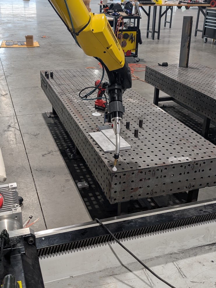
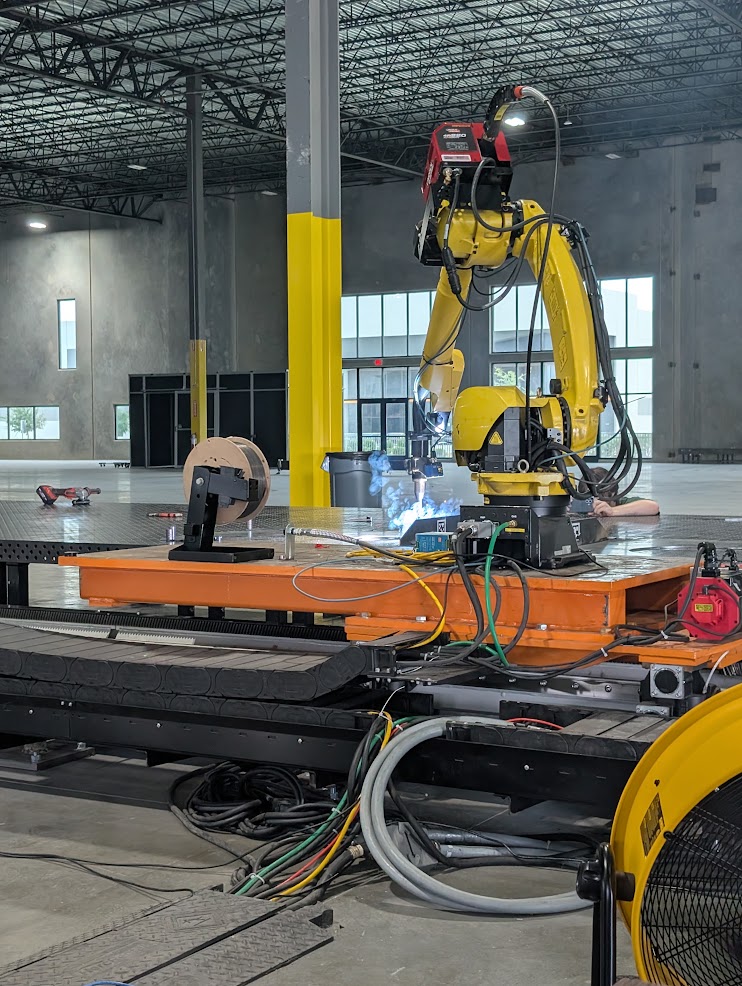
The mechanical work was the parts that connect the robots, their tooling, sensors, and the cell:
- Magnetic end effectors for handling steel plate.
- Sensor mounts and calibration tooling.
- An adapter plate for mounting a FANUC M-710 to the Güdel RTU: bolt patterns to both interfaces, load path, tolerances and fit, and manufacturability.
- Manufacturing drawings for outside fabrication, component sourcing, and vendor RFQs, including pricing, lead times, and procurement.
CAD → fabrication
This is software, in Python on OpenCASCADE (OCP) and CadQuery, that converts ship CAD into data a fabrication cell can act on:
- Ingest of ship-panel CAD (STEP) and decomposition of blocks into panels and parts.
- Laser-cutting DXFs with part IDs, alignment markings, and weld information.
- Weld planning. The joint-detection, conditioning, and stitch-placement algorithms were the team’s prior work, which I ported into the new system. The consumables model and the torch-reach obstruction model were mine: the obstruction model splits a seam only where a third part physically blocks the nozzle.
- A part ID computed from the part’s geometry instead of its file name. The same part gets the same ID no matter how it was placed in the model or which of two CAD kernels loaded it, and mirror-image (port/starboard) parts get different IDs.
- Part lifecycle tracking from ingest through fabrication, on PostgreSQL with SQLAlchemy and Alembic migrations, deployed with Docker.
on2occt, a standalone translator from Rhino.3dm(openNURBS) B-reps into OpenCASCADE solids. On a 198-brep production block it produced 198 closed solids; the existing open-source path produced none.
Block ingest time went from 8:01 to 2:33 over the summer.
Robot telemetry and replay
The cell publishes telemetry (run start/stop, per-signal units, named I/O lines, and scene geometry). I wrote both the side that publishes it and the tool that reads it:
- Producer-side instrumentation in the cell runtime. A simulated run can publish a stream byte-identical to the real cell, so one viewer serves both.
- A desktop viewer in Rust and TypeScript (Tauri) for browsing, plotting, and scrubbing runs: signal plots with expression evaluation, laser-profile cross-sections, and 3D playback of the posed robots. Offline run bundles replay through the same code path as live runs.
I also contributed to the team’s cell simulator. After profiling isolated the bottleneck to JIT code generation rather than the GIL, step time went from 36.7 ms to 5.9 ms, which is faster than real time at full fidelity.
Attribution
The cell, its planning and execution stack, and the original weld-planning algorithms were the team’s. I owned the part-record and CAD-to-fabrication system, on2occt, the telemetry producer and viewer, and the mechanical hardware listed above, and was a contributor to the simulator.