MATADOR is a modular dynamometer I am designing to measure electric motors and custom actuators: torque–speed envelopes, and behavior through a reduction, on one stand with swappable device-under-test (DUT) mounts. It is not built yet. This page covers the design and sourcing work so far.
Requirements
The representative device under test is a robot-actuator-class motor: roughly 21 N·m peak torque and speeds up to about 20,000 rpm at the motor shaft. Those two ends are far apart (high torque at low speed after a reduction, high speed at low torque at the motor); no single sensor or absorber covers both.
Layout and absorber sizing
The absorber is a second motor run as a generator/brake against the DUT. Sizing it means matching the DUT’s torque–speed envelope: enough torque to hold the DUT at its peak, a speed rating that follows it near 20,000 rpm, or a reduction between them that trades one for the other. I worked through the reduction ratios for a gearbox between DUT and absorber versus direct coupling, at different points in the envelope.
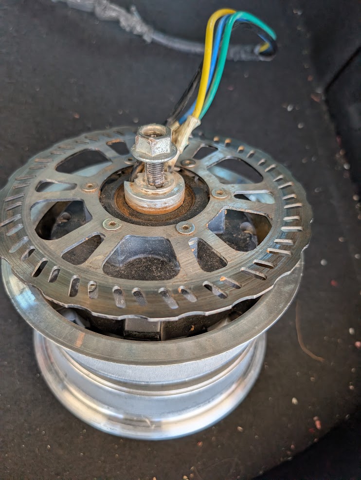
A secondhand ~8 kW motor was acquired as a candidate absorber. Whether it ends up as the absorber depends on its speed rating against the DUT requirement and on the power electronics needed to run it as a generator.
Torque sensing
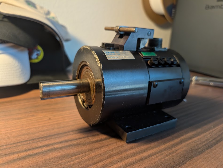
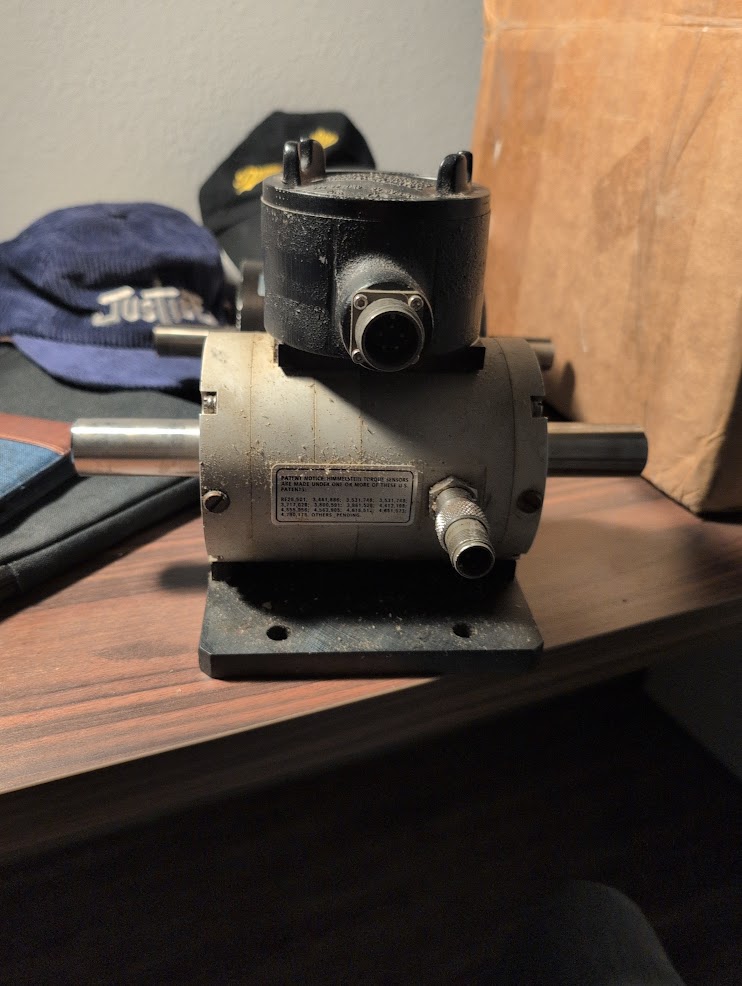
Torque is measured with inline rotary transducers between DUT and absorber. Two sensor classes cover the envelope: roughly 20 N·m to 9,000 rpm for direct high-speed measurement at the motor, and roughly 113 N·m to 5,000 rpm for post-reduction measurement. Lebow and Himmelstein hardware in these classes has been acquired or evaluated. Each transducer has its own speed limit, which sets where in the drivetrain it can sit.
Drivetrain and structure
Between the sensors, DUT, and absorber: couplings that tolerate the misalignment a swappable mount will have, bearings rated for the speed, and a base stiff enough that the torque reaction does not show up as vibration in the readings. Cooling for the absorber under sustained load is part of the sizing, since a braked motor has to dump the DUT’s full output as heat.
DAQ, control, and calibration
The plan is to sample torque, speed, DUT current and voltage, and absorber current together, so efficiency comes from readings taken at the same instant. Absorber control sets the load point; the DUT is swept through its envelope. How to calibrate and run tests (static torque checks before spinning anything, and cross-checks where the two sensor ranges overlap) is still being worked out.
Status
In progress. Requirements, layout, absorber sizing, and torque-sensor selection are done on paper. Torque transducers and a candidate absorber motor have been acquired. Nothing has been assembled or run, and there are no measurement results yet. Next: mechanical design of the base and mounts, and selecting the absorber’s power electronics.