Bent Sheet Metal Cart
Designed and documented a fully sheet-metal pit cart for FRC Team 1086.
Parts were CNC laser cut and CNC brake-formed from 0.125” 5052 aluminum by our sheet metal sponsor, then assembled by the team.
The structure relies on folded geometry for stiffness rather than tube framing.
CAD
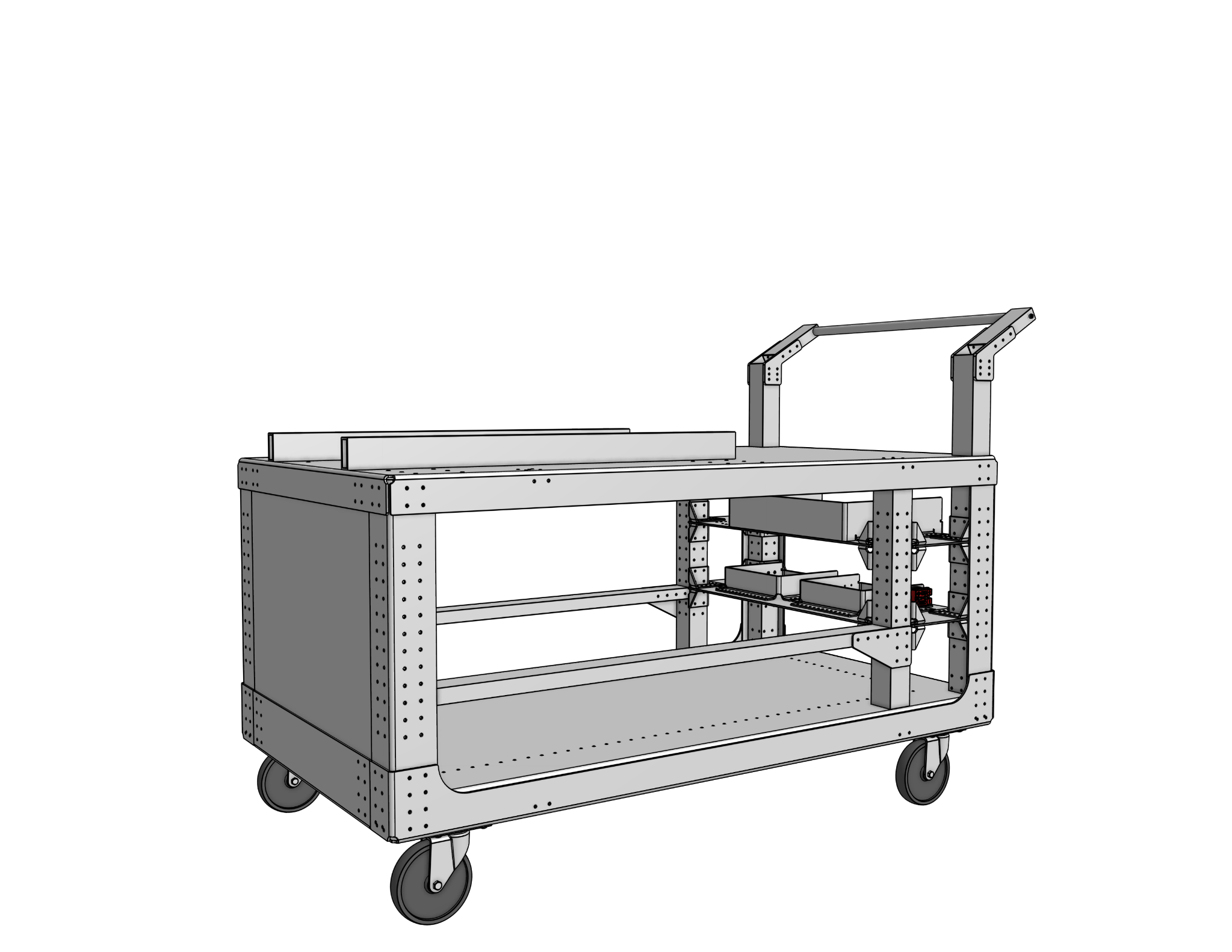
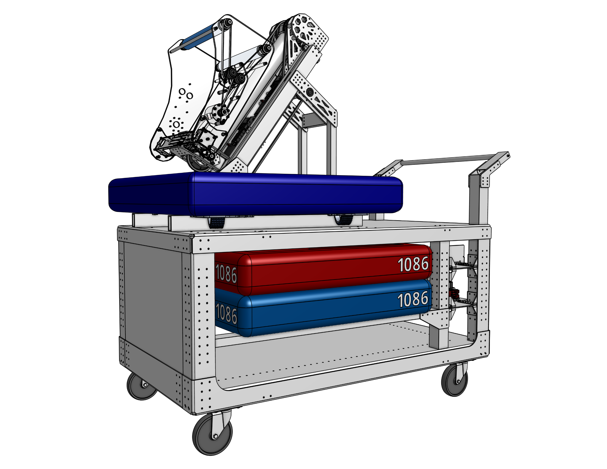
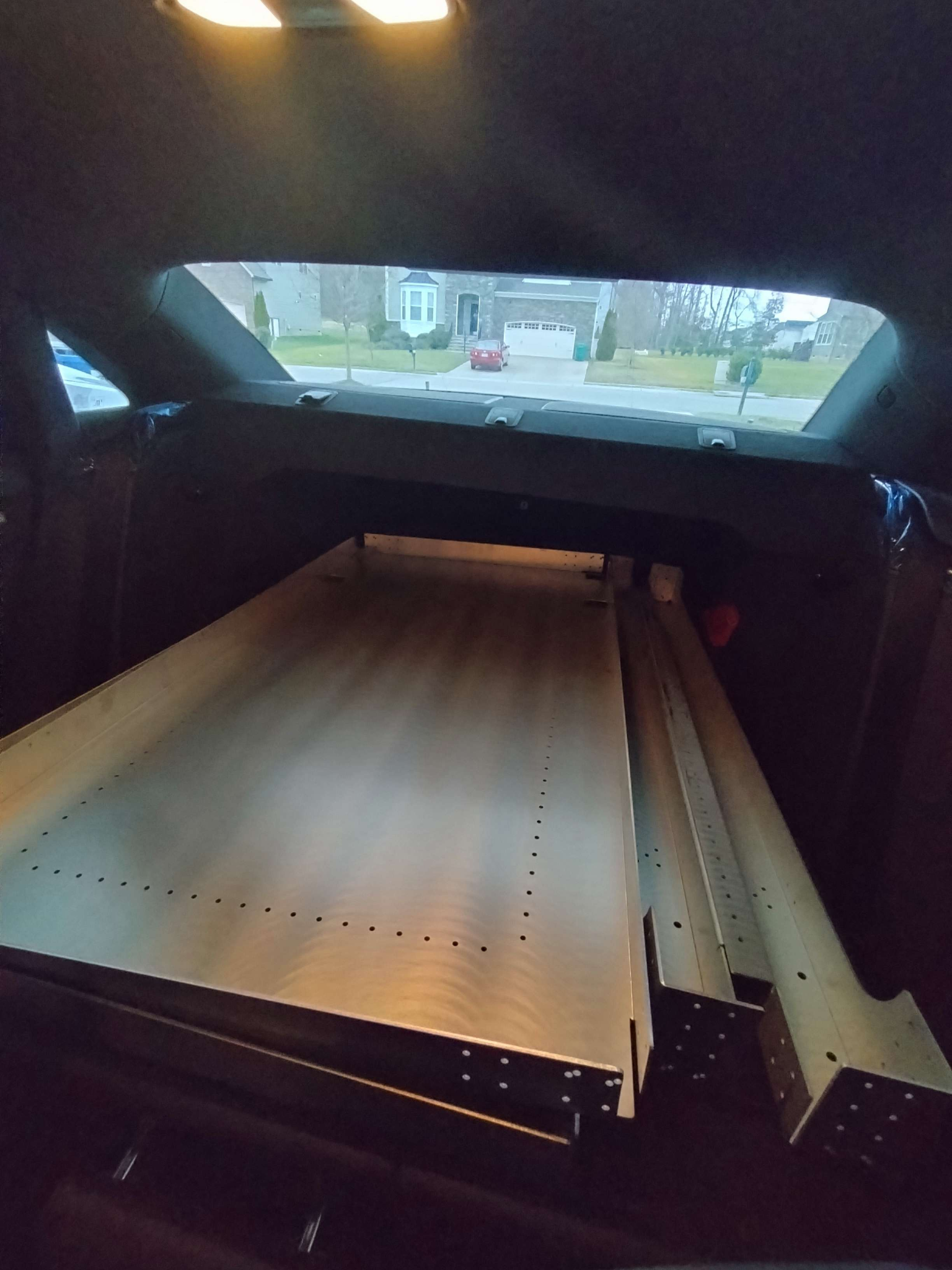
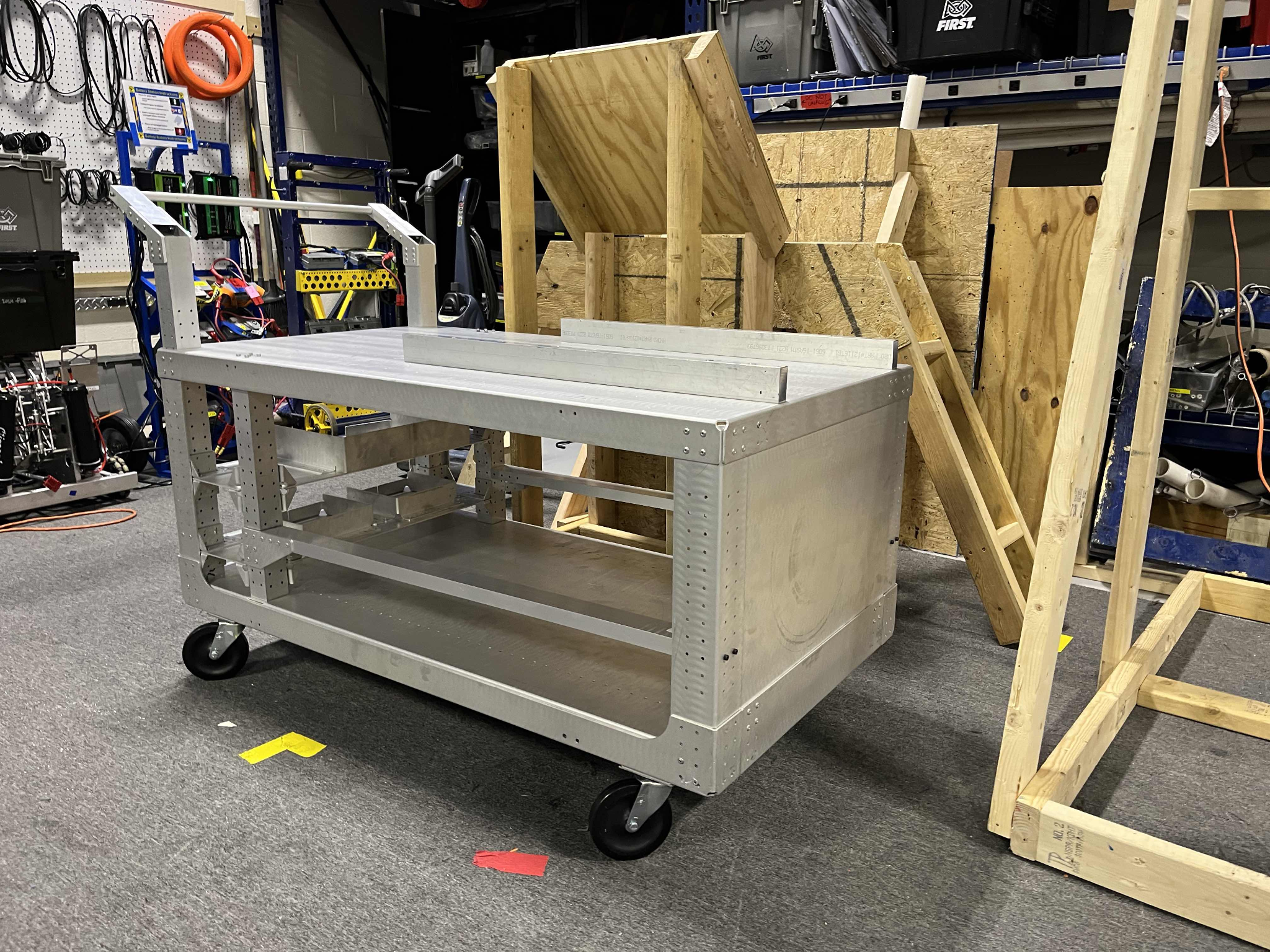
Fabricated Cart
Design Notes
- Material: 0.125” 5052 aluminum sheet
- Manufacturing: CNC laser cutting + CNC press brake forming
- Fastening: Riveted + bolted sheet metal structure
- Modular bumper storage
- Integrated handle structure
- Caster-mounted base
The structure uses flanged panels and bent geometry for rigidity.
Side walls and trays were designed with proper bend radii, corner reliefs, and hole spacing appropriate for 5052-H32.
Manufacturing Workflow
- Modeled flat patterns with bend allowances for 0.125” 5052.
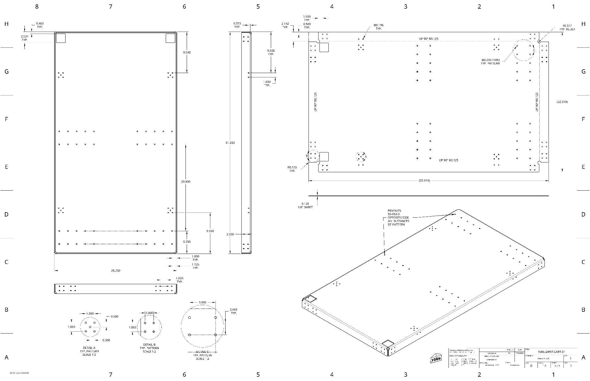
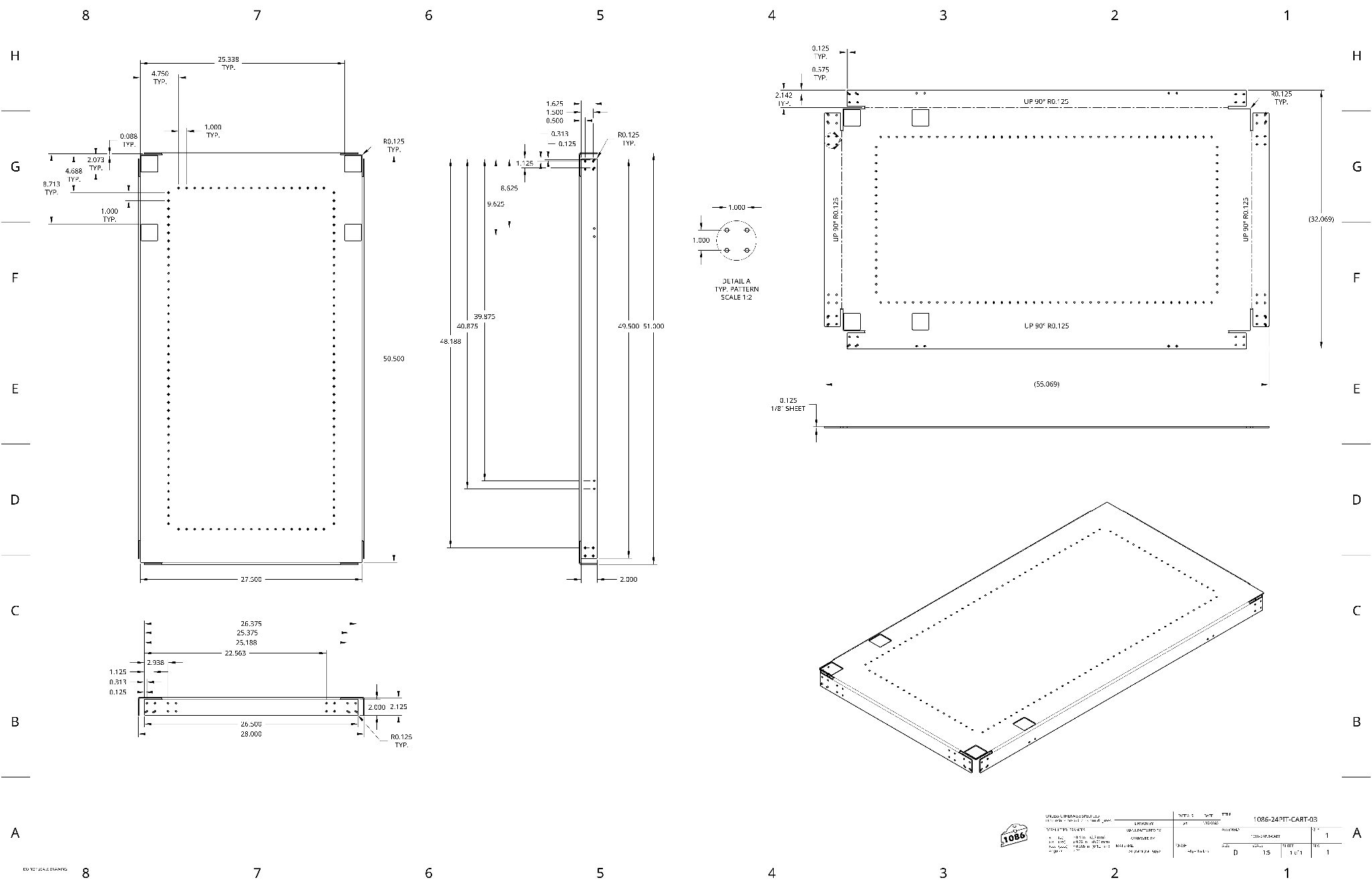
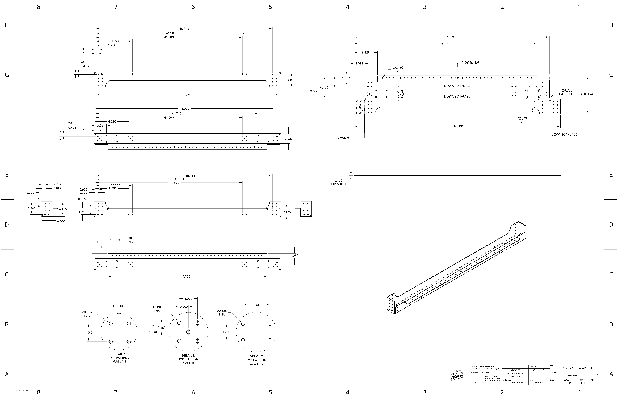
- Produced detailed manufacturing drawings (hole patterns, bend callouts, reliefs).
- Sent DXFs and drawing package to sponsor.
- Parts were laser cut and formed on a CNC brake.
- Team assembled using rivets and hardware.
This project was also an opportunity to develop proper manufacturing drawing practices:
- Clear bend direction notation
- Inside radius callouts
- Pattern detail views
- Tolerance conventions
Drawings
View selected manufacturing drawings